Purpose:
The purpose of use case diagram is to capture the dynamic aspect of a system. But this definition is too generic to describe the purpose. Use case diagrams are used to gather the requirements of a system including internal and external influences. These requirements are mostly design requirements. So when a system is analyzed to gather its functionalities use cases are prepared and actors are identified.The purposes of use case diagrams can be as follows:
- Used to gather requirements of a system.
- Used to get an outside view of a system.
- Identify external and internal factors influencing the system.
- Show the interacting among the requirements are actors.
Use case diagrams are considered for high level requirement analysis of a system. So when the requirements of a system are analyzed the functionalities are captured in use cases. So we can say that uses cases are nothing but the system functionalities written in an organized manner. Now the second things which are relevant to the use cases are the actors. Actors can be defined as something that interacts with the system.
The actors can be human user, some internal applications or may be some external applications. So in a brief when we are planning to draw an use case diagram we should have the following items identified:
- Functionalities to be represented as an use case
- Actors
- Relationships among the use cases and actors.
Use case diagrams are drawn to capture the functional requirements of a system. So after identifying the above items we have to follow the following guidelines to draw an efficient use case diagram.
The name of a use case is very important. So the name should be chosen in such a way so that it can identify the functionality performed.
- Give a suitable name for actors.
- Show relationships and dependencies clearly in the diagram.
- Do not try to include all types of relationships. Because the main purpose of the diagram is to identify requirements.
- Use note when ever required to clarify some important points.
These diagrams are used at a very high level of design. Then this high level design is refined again and again to get a complete and practical picture of the system. A well structured use case also describes the pre condition, post condition, exceptions. And these extra elements are used to make test cases when performing the testing.
The following are the places where use case diagrams are used:
- Requirement analysis and high level design.
- Model the context of a system.
- Reverse engineering.
- Forward engineering.

The following topics describe the relationships that you can use in use case diagrams:
Association relationshipsIn UML models, an association is a relationship between two classifiers, such as classes or use cases, that describes the reasons for the relationship and the rules that govern the relationship.
Generalization relationships
In UML modeling, a generalization relationship is a relationship in which one model element (the child) is based on another model element (the parent). Generalization relationships are used in class, component, deployment, and use case diagrams.
Include relationships
In UML modeling, an include relationship is a relationship in which one use case (the base use case) includes the functionality of another use case (the inclusion use case). The include relationship supports the reuse of functionality in a use case model.
Extend relationships
In UML modeling, you can use an extend relationship to specify that one use case (extension) extends the behavior of another use case (base). This type of relationship reveals details about a system or application that are typically hidden in a use case.
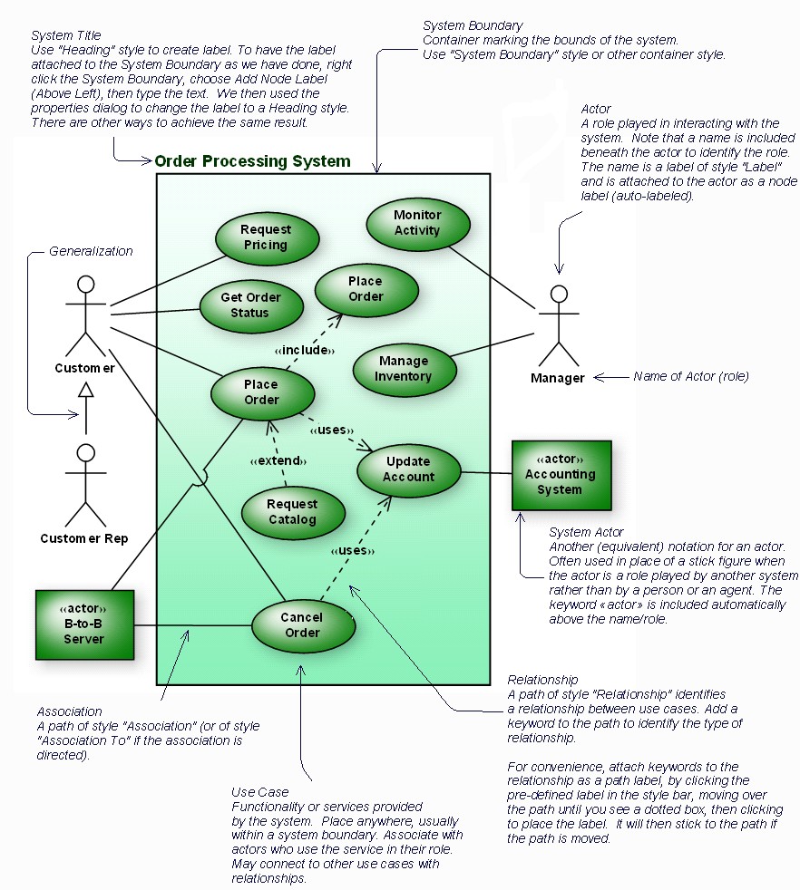 |
| a good diagram i find while googling |
No comments:
Post a Comment